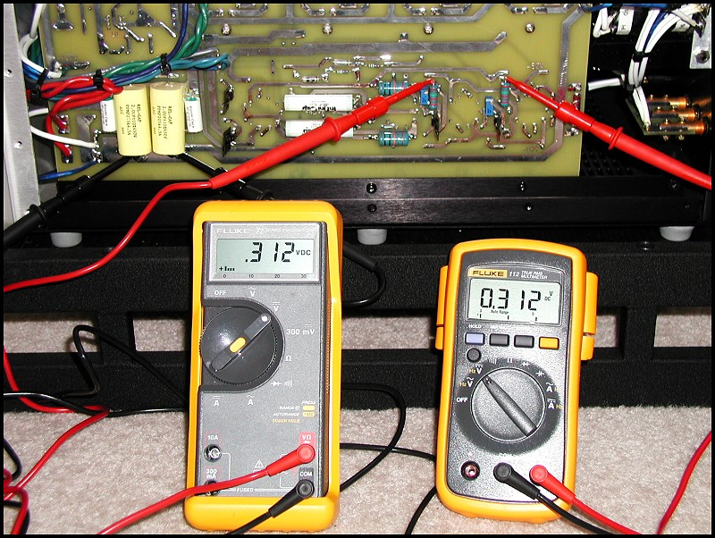
This is where it gets hairy. Notice where the meter test lead clips are attached. The trimpots are those blue rectangular components with the small adjustment screw facing out toward you. You should also refer to the schematic diagram and instrucition sheet (available on the last page of this tutorial). You need to adjust the voltage at these points relative to each other and they should be within 0.01VDC of each other. The voltage at these points affects the +60VDC +/-1VDC plate voltage for each driver tube. You need to adjust the trimpots alternating between the two as you monitor the +60VDC plate voltage and at the same time, each test point needs to track relative to each other to within 0.01VDC. The photo does not represent this correctly. You need to use one multimeter and measure the difference between the junction of R7+8 compared to the junction of R11+12 as described in step 2 of the ARC instruction sheet. This difference voltage should not exceed .01VDC. Click photo to move to next picture.
Return to main Audio Page
Return to Home Page